
Siemens 3RW3013-1BB04
Product description
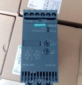 The Siemens 3RW3013-1BB04 is an economical soft starter suitable for three-phase asynchronous motors. It has a rated current of 3.6A, is suitable for a 1.5kW/400V motor, supports a wide voltage input range of 200-480V, and the control power supply is 24V AC/DC (screw terminals). The following is a detailed description of its core functions, operation key points, and fault handling:
I. Core Parameters and Functions
1. **Technical Specifications**
- **Motor Power**: 1.5kW (at 400V), compatible with an input voltage of 200-480V (with a fluctuation of ±10%).
- **Control Power Supply**: 24V AC/DC (supports a voltage fluctuation of ±20%), connected through screw terminals.
- **Protection Functions**: Built-in overload protection, overcurrent protection, undervoltage protection, and supports PTC thermistor motor protection (external sensor required).
- **Starting Modes**: Voltage ramp starting (default), current-limiting starting (the current limit value can be adjusted).
2. **Structural Design**
- **Installation Method**: Supports rail mounting or wall-mounted installation. It is necessary to maintain a vertical installation plane within an inclination range of ±10°.Siemens servo motor 1FL6032-2AF21-1LG1and the SINAMICS V90
- **Protection Level**: IP20, and it needs to be used in a dry indoor environment.
- **Dimensions**: 57mm×125mm×165mm (width×height×depth), and the weight is approximately 3.5kg.
II. Wiring and Installation
1. Main Circuit Wiring
- **Power Input**: Connect L1/L2/L3 to three-phase alternating current (200-480V). Note that the phase sequence does not need to be strictly corresponding.
- **Motor Output**: Connect U/V/W to the motor windings, and ensure that the wiring is firm (recommended wire cross-sectional area: 1.5-2.5mm²).
- **Bypass Contactor**: There is a built-in bypass contactor, and no additional installation is required. The thyristor will be automatically bypassed after the starting is completed.
2. Control Circuit Wiring
- **Control Power Supply**: Connect 24V AC/DC to terminals 1 (+) and 2 (-). Shielded wires need to be used to avoid interference.
- **Start/Stop Signals**:
- **Passive Contacts**: Connect the start signal (such as a button) to terminals 3 and 4 (default normally closed contacts, start when closed).
- **Fault Reset**: Terminals 5 and 6 are used for fault reset (default normally closed contacts, reset when closed).
- **Status Feedback**:
- **Operation Indication**: Terminals 7 and 8 output the operation signal (24V DC).
- **Fault Indication**: Terminals 9 and 10 output the fault signal (24V DC).
3. Installation Precautions
- **Environmental Requirements**: The operating temperature is from -25°C to +60°C, and the storage temperature is from -40°C to +80°C. Avoid dust and corrosive gases.
- **Wiring Specifications**: The main circuit and the control circuit need to be wired separately, with a distance of ≥10cm to prevent electromagnetic interference.
- **Prohibited Operations**: It is not allowed to connect capacitive components (such as reactive power compensation devices) between the soft starter and the motor.
III. Parameter Setting and Debugging
1. Basic Parameters
- **Starting Time**: The default is 5 seconds (adjustable range: 0.5-60 seconds), adjusted according to the load characteristics.
- **Stopping Time**: The default is 3 seconds (adjustable range: 0.5-60 seconds), used to control the voltage drop rate during shutdown.
- **Current Limit Value**: The default is 3 times the rated current (adjustable range: 1.5-5 times), to avoid excessive starting current.
2. Advanced Parameters (Need to be set through the operation panel)
- **Overload Protection Threshold**: The default is 1.15 times the rated current (adjustable range: 0.5-1.5 times), and it needs to be calibrated according to the parameters on the motor nameplate.
- **PTC Sensor Configuration**: If an external PTC thermistor is connected, this function needs to be enabled in the parameters and the trigger temperature needs to be set.
- **Undervoltage Protection**: The default is 70% of the rated voltage (adjustable range: 50%-90%), to prevent equipment damage caused by too low voltage.
3. Operation Panel Instructions
- **LED Indicators**:
- **RUN**: The green light is on during operation.
- **FAULT**: The red light is on in case of a fault and will go out after reset.
- **STATUS**: Flashing indicates that the parameters are being set, and a steady light indicates normal standby.
- **Button Functions**:
- **SET**: Enter the parameter setting menu.
- **▲/▼**: Select parameters or adjust values.
- **RESET**: Reset the fault status.
IV. Fault Diagnosis and Maintenance
1. Common Fault Codes
| Code | Meaning | Possible Causes | Solutions |
| F0001 | Overcurrent | Motor locked rotor, excessive load | Check the mechanical connection of the motor and reduce the current limit value |
| F0002 | Overvoltage | Excessively high input voltage or too fast braking | Check the power supply voltage and extend the stopping time |
| F0003 | Undervoltage | Too low input voltage | Check the stability of the power supply |
| F0004 | Overload | Motor overload or incorrect parameter setting | Check the load and calibrate the overload protection value |
| F0005 | Overheating | Too high ambient temperature or poor heat dissipation | Improve ventilation and reduce the ambient temperature |
2. Maintenance Suggestions
- **Regular Inspections**:
- Check whether the wiring terminals are loose every 6 months and clean the internal dust.
- Test the conduction voltage drop of the thyristor every year (normally about 1.5V). If it is abnormal, the module needs to be replaced.
- **Replacement of Vulnerable Parts**:
- **Bypass Contactor**: The service life is about 100,000 times. When starting frequently, the contact wear needs to be checked regularly.
- **Electrolytic Capacitor**: Replace the filter capacitor of the control circuit every 5 years to prevent voltage fluctuations.
- **Long-term Shutdown**: Disconnect the power supply and power it on for 30 minutes every 3 months to maintain the activity of the electronic components.
V. Typical Application Scenarios
1. **Water Pump Control**: Reduce the water hammer effect through soft starting and extend the service life of the pipeline.
2. **Conveyor Belt Drive**: Smooth starting to avoid goods slipping, and support the synchronous operation of multiple soft starters.
3. **Fan Control**: Reduce the starting current and minimize the impact on the power grid.
VI. Precautions
- **Safe Operation**:
- Wait for 5 minutes after powering off or use a 200Ω/10W resistor to discharge the DC bus capacitor to avoid electric shock.
- Disconnect the main power supply and the control power supply during maintenance to ensure that there is no residual voltage.
- **Compatibility Issues**:
- It does not support the parallel use of the frequency converter and the soft starter, which may lead to harmonic interference.
- If it is necessary to connect to a PLC, it is recommended to isolate the control signal through an intermediate relay.
More recommendations
-
Schneider LC1E400 Contactor
-
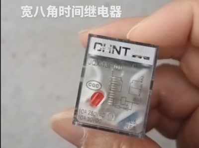
Chint JQX13F Electromagnetic Relay
-
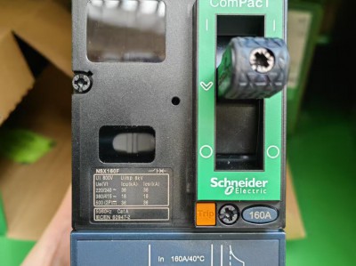
Schneider C16F2TM160 Circuit Breaker
-
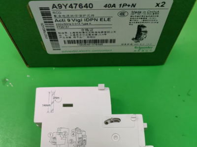
Schneider A9Y47640
-

Schneider LADN04C
-
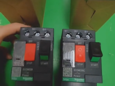
Schneider GV2ME08C motor circuit breaker
-
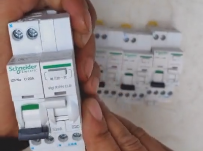
Schneider IDPNa C20A miniature circuit breaker (MCB)
-
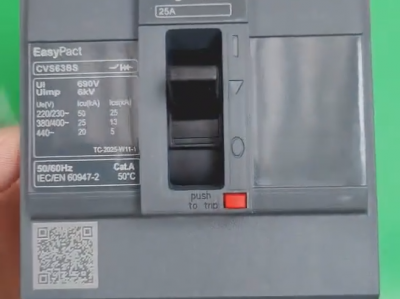
Schneider CVS63BS25A molded case circuit breaker (MCCB)
-
Schneider LC1DT80 4-pole contactors
-
Schneider Electric Circuit Breaker Model A9P28620