
How to Wire the Chint Contactor NXC-09
 The wiring of the Chint contactor NXC-09 should strictly follow the electrical specifications to ensure the correct connection of the main circuit, control circuit, and auxiliary contacts. The following is a detailed operation guide based on the product characteristics and actual application scenarios:
I. Preparation Before Wiring*Schneider Circuit Breakers Price*
1. **Confirm the Model and Parameters**
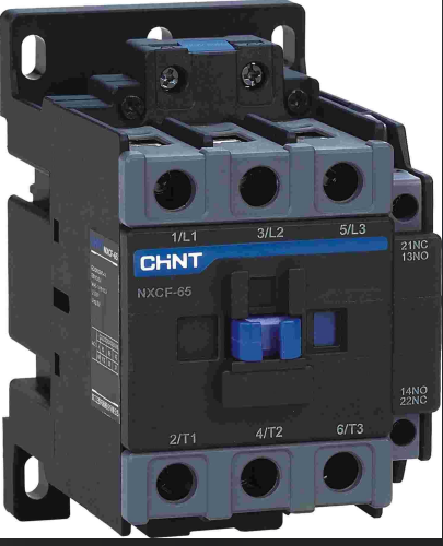
- Check the contactor body or label to confirm that the model is **NXC-09**, the rated current is 9A, and the control coil voltage (such as 220VAC) needs to match the power supply.
- Pay attention to distinguish the main contacts (3 poles) from the auxiliary contacts (usually 1NO + 1NC) to avoid confusion.
2. **Tools and Materials*Chint's NB1-63DC series DC circuit breakers Price*
- Screwdriver, wire stripper, multimeter
- Power cord (the cable meeting the current specification should be used for the main circuit), control wire (it is recommended to use single-strand or multi-strand copper wire of 0.75-1.5mm²)
- Fuse, thermal relay (optional, for circuit protection)
3. **Safety Measures*Chint NXR series thermal overload relays price*
- Disconnect the power supply to ensure that the operation area is dry and free of debris.
- Wear insulated gloves and use an electroscope to detect that there is no voltage in the circuit before operation.
*II. Main Circuit Wiring (Connecting the Load)*CHINT contactor price*
1. **Power Inlet Connection*CHINT surge protector price*
- Connect the live wires (L1, L2, L3) of the three-phase power supply to the **L1, L2, L3** terminals of the contactor (usually located at the top) respectively, and tighten the terminal screws with a screwdriver.
- For a single-phase load, only L1 and N (neutral wire) need to be connected, but it is necessary to confirm that the contactor supports single-phase applications.
2. **Load Outlet Connection*Schneider LRD Thermal Relay Price*
- Connect the three leads of the load (such as a motor) to the **T1, T2, T3** terminals of the contactor (located at the bottom) correspondingly to ensure a firm connection.
- If the load is a single-phase device, connect T1 and N, and skip the other terminals.
3. **Use of Busbars (Optional)**
- If multiple contactors need to be connected in parallel, a special busbar (such as the NXC091218A model) can be used to connect L1-L3 or T1-T3 to simplify the wiring process.
III. Control Circuit Wiring (Achieving On/Off Control)**
1. **Coil Wiring**
- The two terminals **A1** and **A2** of the contactor coil need to be connected to the control power supply. For example, for a 220VAC coil, A1 is connected to the live wire (L), and A2 is connected to the neutral wire (N).
- If the control signal comes from a PLC or a relay, A1 is connected to the output signal terminal, and A2 is connected to the common terminal (COM).
2. **Wiring of Start/Stop Buttons (Taking 220V Control as an Example)**
- **Start Button (Normally Open)**: One end is connected to the live wire (L), and the other end is connected to A1.
- **Stop Button (Normally Closed)**: One end is connected to A2, and the other end is connected to the neutral wire (N).
- **Self-locking Circuit**: Connect the **normally open auxiliary contact (NO)** of the contactor in parallel at both ends of the start button to ensure that the coil remains energized after the button is released.
3. **Wiring of the Protection Circuit (Optional)**
- **Thermal Relay**: Connect the normally closed contact of the thermal relay in series in the control loop, and it will automatically cut off the coil power when the motor is overloaded.
- **Fuse**: Connect a fuse (such as 2A) in series in the control loop to prevent equipment damage caused by a short circuit.
IV. Extended Applications of Auxiliary Contacts**
1. **Signal Feedback**
- Connect the **normally open contact (NO)** to the indicator light circuit to indicate the working status of the contactor (the light on indicates that it is attracted).
- The **normally closed contact (NC)** can be used for interlocking control, for example, to prevent the forward and reverse rotation of the motor from starting simultaneously.
2. **Remote Control**
- Connect an intermediate relay or a PLC module through the auxiliary contacts to achieve remote monitoring or automatic control.
V. Inspection and Testing After Wiring**
1. **Appearance Inspection**
- Confirm that all terminal screws have been tightened, and there is no exposed or loose wire.
- Check whether the auxiliary contacts are flexible and there is no jamming phenomenon.
2. **On/Off Test**
- Use the ohmmeter gear of the multimeter to measure the coil resistance (a 220V coil is about several hundred ohms). If it is infinite or short-circuited, it indicates that the coil is damaged.
- Manually press the contactor core and measure the on/off status of the main contacts and auxiliary contacts to ensure normal operation.
3. **Power-on Test**
- Connect the main power supply and the control power supply, and observe whether the contactor is normally attracted and whether the load is running.
- Test the start/stop buttons and protection functions to verify the correctness of the circuit logic.
VI. Precautions and Troubleshooting**
1. **Common Errors**
- **Wrong Coil Voltage Connection**: For example, connecting a 220V coil to a 380V power supply, resulting in the coil being burned out.
- **Confusion between Main Contacts and Control Contacts**: Mistakenly connecting the load to the A1/A2 terminals, or connecting the control wire to the L1/L2 terminals.
2. **Troubleshooting**
- **Contactor Not Attracted**: Check whether the coil voltage, fuse, button, and thermal relay contacts are normal.
- **Serious Contact Arcing**: Clean the contact surface and check whether the load current exceeds the rated value.
- **Auxiliary Contact Failure**: Replace the auxiliary contact module or check whether the wiring is loose.
3. **Maintenance Suggestions**
- Regularly clean the oxide layer on the contact surface to ensure good electrical conductivity.
- Check the tightness of the wiring terminals to prevent loosening caused by vibration.
**VII. Typical Application Case (Motor Start/Stop Control)**
1. **Circuit Schematic Diagram**
```
Power L ── Fuse ── Stop Button (Normally Closed) ── Start Button (Normally Open) ── A1
A2 ── Normally Closed Contact of Thermal Relay ── Power N
At the same time, the NO contact of the contactor is connected in parallel at both ends of the start button.
2. **Operation Process**
- Press the start button, the contactor is attracted, the motor runs, and the NO contact is self-locked.
- Press the stop button, the contactor is released, and the motor stops.
- If the motor is overloaded, the thermal relay acts and cuts off the control loop.
Through the above steps, the wiring of the NXC-09 contactor can be completed safely and efficiently. If you are not familiar with complex circuits (such as forward and reverse rotation control), it is recommended that a professional electrician operate, or refer to the wiring manual provided by Chint officially.