
assembling a distribution box with an electricity meter
Product description
 According to your requirements (assembling a distribution box with an electricity meter, combined with the previously mentioned **NXBLE1-63/2P-63A circuit breaker with a CE mark**), the following are the detailed assembly steps, material list, and precautions to ensure compliance with safety regulations and CE standards:
I. List of Required Materials
1. **Main Body of the Distribution Box**
- Dimensions: Select according to the number of electricity meters and circuit breakers (it is recommended to reserve a 20% redundant space, for example, a 2-4 circuit distribution box).
- Material: Metal (which needs to be grounded) or flame-retardant plastic, with a CE certification (ensuring compliance with standards such as EN 62208).
2. **Electricity Meter**
- Type: Single-phase 220V electricity meter (confirm whether it is suitable according to the local voltage, which is 120V/240V in Los Angeles, USA), with a CE certification (complying with standards such as EN 50470).
- Specification: Rated current ≥ 63A (matching the main circuit breaker), and supporting terminal connection at the incoming line end.
3. **Circuit Breaker and Accessories**
- Main Circuit Breaker: NXBLE1-63/2P-63A (residual current circuit breaker, 2 poles, 63A, with a CE mark).
- Branch Circuit Breakers: Configure according to requirements (such as 16A/1P for lighting, 20A/1P+N residual current protection for sockets, etc.), all of which require CE certification.
- Installation Rail: 35mm standard rail (suitable for circuit breakers).
4. **Wires and Wiring Materials**
- Incoming Line Cable: According to the specification of the incoming household power supply (for example, commonly used 10AWG or 8AWG copper wires in the United States, and the withstand voltage should be ≥ 600V).
- Branch Circuit Wires: 14AWG for lighting, 12AWG for sockets, and the ground wire (yellow-green double-color, with a cross-sectional area ≥ 50% of the phase wire).
- Wiring terminals, insulating tape, wire lugs (copper terminals), and number tubes (identifying the purpose of the circuits).
5. **Other Accessories**
- Ground busbar and neutral busbar (made of metal with an insulating base).
- Isolating switch (optional, installed between the electricity meter and the main circuit breaker for easy maintenance).
- Screws and expansion bolts (for fixing the box body and internal components).
II. Assembly Steps (Operate According to CE Standards)
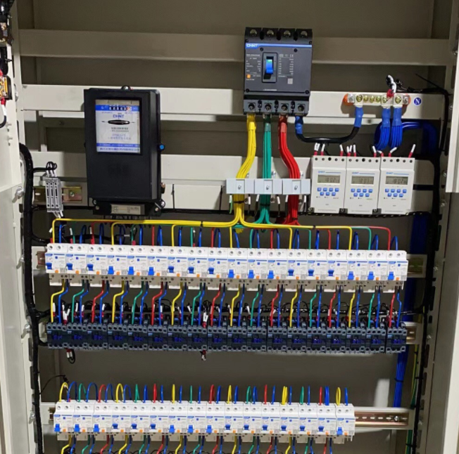
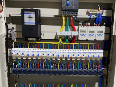
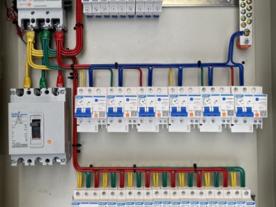
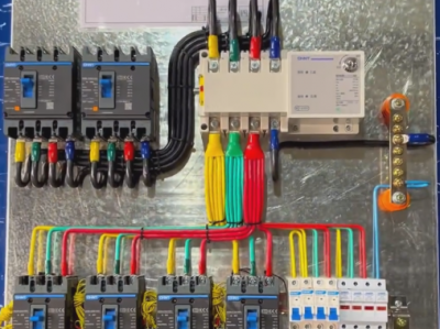
1. Layout Design of the Distribution Box
- **Upper Layer**: Install the electricity meter (incoming line on the left, outgoing line on the right), and ensure that the meter window faces outward for easy reading.
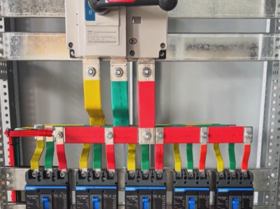
- **Middle Layer**: Install the main circuit breaker (NXBLE1-63/2P-63A), fix it on the rail, and place it below the outgoing line end of the electricity meter.
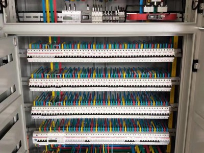
- **Lower Layer**: Branch circuit breakers (divided by function, such as lighting, sockets, air conditioners), install them side by side on the rail, and connect the outgoing line of the main circuit breaker to the incoming line of the branch circuit breakers.
- **Bottom/Side**: Ground busbar (connecting the box body shell and the ground wire), and neutral busbar (connecting the neutral wires centrally).
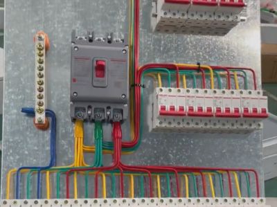
2. Wiring Steps (Operate with the power cut off!)
- **Wiring of the Electricity Meter**:
- Incoming Line End: L1 (phase wire), N (neutral wire) come from the outdoor power supply, and PE (ground wire) is connected to the ground busbar.
- Outgoing Line End: L1 and N are connected to the incoming line end of the main circuit breaker (pay attention to the principle of "incoming from the upper part and outgoing from the lower part" of the circuit breaker).
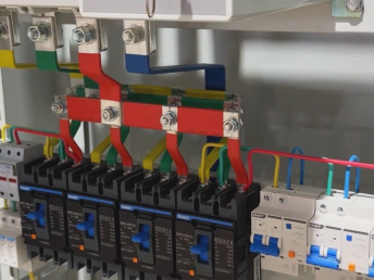
- **Main Circuit Breaker and Branch Circuit Breakers**:
- The outgoing line end (L, N) of the main circuit breaker is connected to the incoming line end of the branch circuit breakers (if the branch circuit breaker is a 1P circuit breaker, only connect the phase wire, and the neutral wire is uniformly connected to the neutral busbar).
- For residual current circuit breakers (such as those for socket circuits), the N wire needs to be connected separately to ensure that the neutral wire is not bridged to other circuits.
- **Ground Wire Connection**:
- The metal shells of all devices, the box body, and the neutral busbar (if required) all need to be connected to the ground busbar through the PE wire, and the ground busbar is connected to the building grounding system through a copper wire with a cross-sectional area of ≥ 4mm².
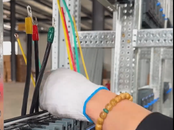
3. Wire Processing and Identification
- The length of stripping the wire should be appropriate to avoid the exposed conductor being too long; the copper wire needs to be crimped with a copper terminal to ensure good contact.
- Use number tubes to mark the purpose of each wire (such as "L of the electricity meter incoming line", "L1 of the socket circuit"), which is convenient for later maintenance.
4. Safety Inspection
- Test the residual current protection function: Press the "Test" button of the main circuit breaker, and it should trip immediately.
- Measure the insulation resistance: Use a megohmmeter to detect that the resistance between the phase wire and the neutral wire, and between the phase wire and the ground wire is ≥ 0.5MΩ.
- Check the grounding of the box body: Ensure that the ground busbar is electrically conductive with the box body, and the grounding resistance ≤ 4Ω (according to local standards).
III. Key Points of CE Certification Compliance
1. **Component Compliance**
- All electrical components (electricity meters, circuit breakers, distribution boxes) need to have a CE mark and comply with the following standards:
- Electricity Meter: EN 50470 (safety of electricity meters), EN 61010 (safety of measuring equipment).
- Circuit Breaker: EN 60898 (household circuit breakers), EN 61008 (residual current devices).
- Distribution Box: EN 62208 (safety of low-voltage distribution boxes).
2. **Installation Compliance**
- The colors of the wires comply with the CE standard (phase wire L1 = brown, N = blue, PE = yellow-green double-color).
- The torque of the wiring terminals complies with the manufacturer's requirements (to avoid being too tight or loose).
- The protection level of the box body is ≥ IP30 (to prevent the entry of solid foreign objects), and if it is installed in a humid environment, a higher protection level is required (such as IP54).
IV. Precautions
1. **Professional Operation**: If you are not a licensed electrician, it is recommended that an electrician with a CE-certified installation qualification perform the operation to ensure compliance with the electrical regulations of the European Union and the local area in the United States (such as the NEC standard).
2. **Voltage Matching**: In Los Angeles, USA, the power supply is a single-phase three-wire system of 120V/240V, and it is necessary to confirm that the electricity meter and the circuit breaker support this voltage (a 2P circuit breaker usually supports 240V, and a 1P circuit breaker supports 120V).
3. **Load Calculation**
- The total load current = the sum of the currents of each branch circuit, and it needs to be ≤ 80% of the rated current (63A) of the main circuit breaker (that is, ≤ 50.4A).
- For example: The total load of 6 branch circuits with 20A each needs to be ≤ 50.4A to avoid overloading.
4. **Identification and Documents**
- Paste the circuit diagram on the inner side of the box door, indicating the load and parameters of the protection devices of each circuit.
- Keep the certificates of conformity of the components and the CE certificates for inspection.
V. Example Circuit Diagram (Single-Phase System)
Outdoor Power Supply (L/N/PE) → Electricity Meter (Incoming Line End) → Main Circuit Breaker (NXBLE1-63/2P-63A) →
Branch Circuit Breaker 1 (16A/1P for Lighting) → Lighting Circuit
Branch Circuit Breaker 2 (20A/1P+N Residual Current for Sockets) → Socket Circuit
Branch Circuit Breaker 3 (32A/1P for Air Conditioner) → Air Conditioner Circuit
(All N wires are connected to the neutral busbar, and PE wires are connected to the ground busbar)
Through the above steps, the assembly of the distribution box with an electricity meter that complies with the CE standard can be completed, ensuring safety, compliance, and easy maintenance. If there are any uncertainties, it is recommended to consult a professional electrician or a certification institution.
Previous:distribution box of the NXBLE1-63/2P-63A circuit breaker
Next:The meaning of the last four digits of the CHINT AC contactor CJX2
More recommendations
-
Distribution Cabinet with Chint Dual-Power Switch
-
Customize XL-21 Power Distribution Cabinets with Inner Doors for China Electric in Hebei
-
Customized Distribution Boxes with Delixi Components
-
distribution box with Chint manual toggle switch
-
assembling a distribution box with an electricity meter
-
distribution box of the NXBLE1-63/2P-63A circuit breaker
-
Customizing GGD power distribution cabinets
-
power distribution cabinet with NH40SZ-4P-300A dual power
-
10KVA High Voltage Switchgear
-
Low voltage switchgear