
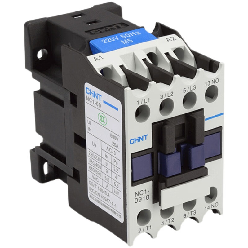
CHINT Contactor NC1-09
Product description
Here is the English translation of the provided text:
CHINT Contactor NC1-09 is a low-voltage electrical appliance suitable for industrial control fields. The core information is organized as follows:
Core Technical Parameters
1. **Rated Current**: 9A (under AC-3 usage category), suitable for controlling small motors (e.g., below 3kW).
2. **Contact Configuration**: 3-pole main contacts (3NO) + 1 set of auxiliary normally open contacts (1NO). Auxiliary modules (such as F4 series) can be expanded for more functions.
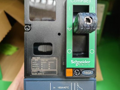
3. **Coil Parameters*Schneider-MCCB-NSX250F-4P-250A*:
- AC coil voltage: 220VAC (50Hz); some models support DC24V.
- Power consumption: Starting power approx. 65VA, holding power approx. 8VA.
4. **Voltage Range**: Rated operating voltage up to 690V, compliant with IEC/EN 60947-4-1 and GB/T 14048.4 standards.
5. **Environmental Conditions*Schneider Circuit Breakers Price*
- Temperature: -5°C to +40°C, humidity ≤90% (no condensation).
- Pollution degree: 3, installation category:
Application Scenarios Chint's NB1-63DC series DC circuit breakers Price*
1. **Motor Control**: Suitable for AC motors with frequent starting and stopping (e.g., water pumps, fans), and can form an electromagnetic starter with thermal overload relays (such as NR series).
2. **Industrial Automation**: Used to control circuits of production line equipment, valves, conveyor belts, etc., requiring remote operation.
3. **Air Conditioning Systems**: Some models are marked "special for air conditioners," adapting to the control needs of refrigeration equipment.
Installation and Use
1. **Wiring Method*Chint NXR series thermal overload relays price*
- Main circuit: L1/L2/L3 for input, T1/T2/T3 for output.
- Control circuit: Coil terminals A1/A2; auxiliary contacts 13/14 (normally open), 21/22 (normally closed).
- Recommended wire cross-section: 2.5mm² for the main circuit, 1.5mm² for the control circuit.
2. **Installation Method*CHINT surge protector price*:
- Supports 35mm standard rail installation or screw fixing; installation surface inclination ≤±5°.
3. **Precautions**:
- Confirm that the coil voltage matches the actual power supply before installation to avoid damage from incorrect wiring.
- Regularly inspect the contact status and clean dust to ensure reliable operation.
Certifications and Compliance
1. **Domestic Certification**: Passed CCC certification, compliant with Chinese low-voltage electrical standards.
2. **International Certifications**:
- Compliant with IEC standards; some models have obtained TÜV explosion-proof certification (suitable for specific industries).
- **Notes for the U.S. market**: Whether NC1-09 has passed UL certification is currently unclear. It is recommended to check via the UL official website or contact CHINT for confirmation. For use in the U.S., consider matching with a UL-certified transformer (e.g., 220V to 110V) to solve voltage adaptation issues.
、Price and Purchase
1. **Domestic Price**: Approximately 64-77 RMB per unit (slightly different across channels).
2. **International Procurement**:
- Contact via WhatsApp: 0086-13811255435.
- U.S. users can contact WhatsApp: 0086-13811255435 for procurement, but note transportation costs and certification compliance. 、Alternative Models and Upgrades
1. **Alternative Models**:
- **NC2 series**: Suitable for higher current scenarios (e.g., 115A~800A), with lower power consumption and smaller arcing distance.
- **NXC series**: New-generation contactor, compatible with CJX2 installation dimensions, supporting wide voltage input (e.g., 24V~480V).
2. **Upgrade Suggestions**: For North American voltage adaptation, choose NC1 series models with 110V coils (e.g., NC1-0910 110V) or use with a transformer.
Manuals and Technical Support
1. **User Manual**: Download *CHINT NC1-09~95 AC Contactor Instruction Manual*, including wiring diagrams, installation dimensions, and fault troubleshooting guides.
2. **Technical Services**: CHINT provides global technical support. Consult the official website or customer hotline for product adaptation, certification, etc.
**Summary**: NC1-09 is a cost-effective contactor suitable for conventional industrial control scenarios. For use in the U.S., it is recommended to prioritize confirming the UL certification status and selecting an adaptation plan based on actual voltage requirements. For long-term projects, consider upgrading to the NXC series for broader compatibility and reliability.
Installation Steps for CHINT Contactor NC1-09
The installation of CHINT Contactor NC1-09 must strictly follow electrical safety specifications. The detailed steps based on official manuals and practical operation experience are as follows:
Pre-installation Preparations
1. **Tools and Materials**:
- Essential tools: 35mm rail (if using rail installation), M3.5 screwdriver, torque wrench (set to 0.8N·m), needle-nose pliers, multimeter.
- Materials: 2.5mm² main circuit wires, 1.5mm² control circuit wires, wire ferrules (matching the wires), insulating tape.
- Optional auxiliary modules: F4 series auxiliary contact groups (e.g., F4-20), thermal overload relays (e.g., NR series).
2. **Environmental Inspection**:
- Ensure the installation environment temperature is -5°C to +40°C, humidity ≤90% (no condensation), pollution degree 3.
- The installation surface must be flat, vibration-free, with an inclination ≤±5°, and leave at least 50mm of heat dissipation space around.
3. **Product Inspection**:
- Verify the model (NC1-09) and coil voltage (e.g., 220VAC); check that contacts are free of oxidation and the casing is undamaged.
- Confirm that auxiliary modules are compatible with the contactor (e.g., F4 series is suitable for NC1-09).
Installation Steps
Fixing the Contactor
1. **35mm Rail Installation**:
- Align the rail卡扣 (rail clips) on the back of the contactor with the 35mm standard rail, push firmly along the rail direction until a "click" locking sound is heard.
- Use a torque wrench to tighten the rail fixing screws (M3.5, torque 0.8N·m) in a diagonal order to ensure the contactor fits tightly with the rail.
2. **Screw Fixing**:
- Mark the installation hole positions on the mounting plate (reference dimension diagram: width 50mm, hole pitch 34mm), drill holes, and install M4 screws.
- Tighten the screws gradually in 2-3 steps (torque 0.8N·m) to avoid deformation due to stress concentration.
Wiring Operations
1. **Main Circuit Wiring**:
- **Input end**: Connect three-phase power cables (L1/L2/L3) to the upper main contacts (L1/L2/L3) of the contactor, and tighten M3.5 screws with a screwdriver (torque 0.8N·m).
- **Output end**: Connect the load (e.g., motor) to the lower main contacts (T1/T2/T3), ensuring the wire cross-section ≥2.5mm² and the wire ferrules are crimped firmly.
2. **Control Circuit Wiring**:
- **Coil wiring**: Connect the control power supply (e.g., 220VAC) to the coil terminals A1/A2. Ensure the voltage matches the contactor's label to avoid burning the coil.
- **Auxiliary contacts**: Normally open contacts (13/14) can be used for self-locking or signal feedback; normally closed contacts (21/22) for interlocking. After wiring, check that the contacts move flexibly.
3. **Auxiliary Module Installation (Optional)**:
- **Top installation**: Remove the top cover of the contactor, align the F4 auxiliary contact group with the slot, press until locked, and connect control wires to the corresponding terminals (e.g., NO contact of F4-20).
- **Side installation**: Loosen the side fixing screws, insert the NCF1-11C module, tighten the screws, and connect control wires.
Testing and Debugging
1. **Pre-power-on Inspection**:
- Use a multimeter to measure the phase-to-phase resistance of the main circuit (should be infinite) and the coil resistance of the control circuit (approx. 2.7kΩ for 220VAC models).
- Manually press the contactor armature to check if the main and auxiliary contacts act synchronously without jamming or abnormal noise.
2. **Function Testing**:
- Disconnect the main circuit power, apply rated voltage (e.g., 220VAC) to the coil, observe whether the contactor pulls in reliably, and check if the auxiliary contact status is correct.
- Measure the coil power consumption (starting power approx. 65VA, holding power approx. 8VA) to ensure consistency with the parameters.
3. **Load Testing**:
- Connect loads such as motors, gradually increase the current to the rated value (9A), and check that the contact temperature rise ≤60K with no abnormal heating or arcing.
Precautions
1. **Safety Operations**:
- Always cut off the power supply during installation and maintenance to avoid electric shock risks.
- Prohibit use in flammable and explosive environments; select TÜV-certified models for explosion-proof scenarios.
2. **Voltage Adaptation**:
- U.S. users must confirm the coil voltage (e.g., choose 110V models or use with a transformer) and verify UL certification (NC1-09's UL certification is currently unclear).
3. **Long-term Maintenance**:
- Inspect contact wear every 6 months, clean oxidation layers with fine sandpaper, and ensure contact resistance ≤50mΩ.
- Calibrate the coil pull-in voltage (85%~110% rated voltage) and release voltage (20%~75% rated voltage) annually.
Common Problem Handling
- **Contactor fails to pull in**: Check if the coil voltage is normal, control wires are open, or contacts are oxidized.
- **Contact ablation**: Reduce the operation frequency (≤1200 times/hour under AC-3 category) or upgrade to the NXC series (lower power consumption).
- **Auxiliary module failure**: Re-plug the module, check for loose wiring, and replace the module if necessary.
Following the above steps ensures the safe and reliable operation of the NC1-09 contactor. It is recommended to keep installation records and regularly refer to the *CHINT NC1-09~95 AC Contactor Instruction Manual* (2025 edition) to update maintenance strategies.
More recommendations
-
Schneider LC1E400 Contactor
-
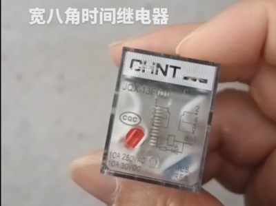
Chint JQX13F Electromagnetic Relay
-
Schneider C16F2TM160 Circuit Breaker
-
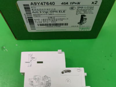
Schneider A9Y47640
-
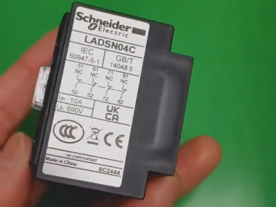
Schneider LADN04C
-
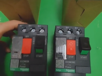
Schneider GV2ME08C motor circuit breaker
-
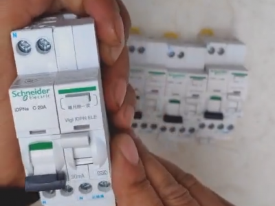
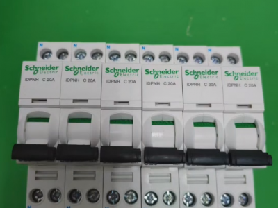
Schneider IDPNa C20A miniature circuit breaker (MCB)
-
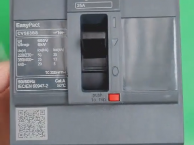
Schneider CVS63BS25A molded case circuit breaker (MCCB)
-
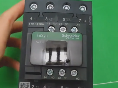
Schneider LC1DT80 4-pole contactors
-
Schneider Electric Circuit Breaker Model A9P28620