
Siemens V20 Inverter 15KW of Model 6SL3210-5BE31-5UV0
Product description
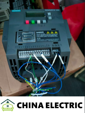 The Siemens V20 inverter of model **6SL3210-5BE31-5UV0** (Note: The last digit "O" in the model provided by the user should be the number "0") is a general-purpose 15kW inverter suitable for three-phase 380-480V power supplies, specifically designed for simple speed regulation applications. The following are its detailed information and usage suggestions:
I. Core Parameters and Functions
1. **Electrical Specifications*Chint converters (NVF2G-18.5/TS4 or NVF2G-18.5/PS4)*
- **Input Voltage**: Three-phase 380-480V (with a fluctuation range of -15%/+10%), compatible with a grid frequency of 47-63Hz.
- **Output Power**: 15kW, supporting 150% overload for 60 seconds continuously (meeting the starting requirements of loads such as fans and water pumps).
- **Control Mode**: V/f control (supporting linear and square V/f curves), with a built-in PID controller, suitable for closed-loop regulation of pressure and flow.
- **Communication Interface**: Standard RS485 interface, supporting USS and Modbus RTU protocols, and can communicate directly with PLCs such as S7-200 SMART and S7-1200.
2. **Hardware Configuration*AB Inverter 25B-D043N114*
- **I/O Interface**: 4 digital inputs (DI), 2 digital outputs (DO), 2 analog inputs (AI, 0-10V/4-20mA), and 1 analog output (AO, 0-20mA).
- **Protection Level**: IP20 (UL open type), which needs to be installed in the control cabinet to avoid direct contact with dust or liquid.
- **Dimensions and Weight**: Frame model FSD, dimensions 240×207×173mm (H×W×D), and the weight is approximately 3.98kg.
3. **Energy Saving and Reliability*https://youtube.com/shorts/bgCeDTDzihY*
- **Built-in Braking Unit**: Models below 15kW integrate a braking unit, eliminating the need for external resistors and reducing costs.
- **Wide Temperature Operation**: The operating temperature range is from -10°C to +50°C (without derating), adapting to harsh industrial environments.
- **Automatic Energy Optimization (AEO)**: By reducing the no-load magnetic flux of the motor, energy consumption is reduced, which is suitable for light-load operation scenarios.
II. Typical Application Scenarios
1. **Industrial Field**
- **Fans and Water Pumps**: Achieve flow/pressure regulation through PID control, with significant energy-saving effects (such as HVAC systems and water treatment equipment).
- **Conveyor Belts and Conveyors**: Support multi-speed control, suitable for equipment such as packaging machines and sorting machines.
- **Mixers and Crushers**: Simple speed regulation requirements, without the need for complex dynamic responses.
2. **Commercial and Civil Use**
- **Elevator Drive**: Support S-curve acceleration and deceleration to improve operation smoothness (cooperating with braking resistors is required).
- **Air Conditioning Compressors**: Automatically adjust the frequency according to the load to reduce energy consumption.
III. Operation and Maintenance
1. **Debugging Tools**
- **BOP Panel**: Built-in basic operation panel, supporting local parameter setting, status monitoring, and fault diagnosis.
- **Smart Connection Module**: A WiFi module can be optionally configured (purchased separately), and wireless debugging can be carried out through a web browser, supporting parameter cloning and remote monitoring.
2. **Parameter Setting**
- **Quick Debugging**: Enter the debugging mode through P0010, and set motor parameters (P0304-P0311), control mode (P1300), acceleration and deceleration times (P1120/P1121), etc.
- **Application Macros**: Preset macros such as "Fan/Water Pump" and "Conveyor Belt" to simplify parameter configuration.
3. **Troubleshooting**
- **Common Fault Codes**:
- **F0001 (Overcurrent)**: Check the motor load, cable connection, or extend the acceleration and deceleration times.
- **F0002 (Overvoltage)**: Extend the deceleration time or add a braking resistor (external resistors are required for models below 15kW).
- **F0003 (Undervoltage)**: Check the stability of the grid voltage and adjust P0210 (input voltage setting).
- **Diagnostic Tools**: View real-time fault information through the Web interface of the smart connection module, or use the fault recording function of the BOP panel.
IV. North American Market Information
1. **Suppliers and Prices**
- **Authorized Dealers**: Viking Electric, TSI Solutions, etc., with a price of approximately **$1,771** (including the BOP panel, excluding tax and freight).
- **Alternative Models**: If higher performance is required, it can be upgraded to SINAMICS G120C (supporting vector control and PROFINET communication).
2. **Compliance**
- **Certification**: Complies with UL standards and is suitable for the North American market.
- **Document Acquisition**: Visit [Siemens Industrial Mall]
V. Precautions
1. **Installation Requirements**
- **Heat Dissipation Space**: It needs to be installed vertically, with at least 100mm of heat dissipation clearance reserved at the top and bottom.
- **EMC Filtering**: If used in a sensitive environment, it is recommended to install an incoming line reactor (such as 6SL3201-0BE31-5AA0).
2. **Compatibility Limitations**
- **Communication Protocol**: Only supports USS and Modbus RTU, and does not directly support PROFINET or EtherNet/IP.
- **Control Precision**: Without encoder feedback, the dynamic response is weak, and it is not suitable for high-precision speed regulation (such as machine tools).
3. **Discontinuation Status**: The current model **6SL3210-5BE31-5UV0** is still an Active product of Siemens and can be purchased normally.
The following are the detailed technical parameters of the Siemens SINAMICS V20 inverter of model **6SL3210-5BE31-5UV0** (15kW), compiled in combination with official documents and actual application scenarios, covering key dimensions such as electrical performance, control functions, interface configuration, and environmental adaptability:
I. Electrical Performance Parameters
1. Input Characteristics
- **Voltage Range**: Three-phase 380-480V (with a fluctuation range of -15%/+10%), compatible with a grid frequency of 47-63Hz.
- **Input Current**:
- **Rated Value**: Approximately 31A (matching a 15kW motor).
- **Peak Value**: 150% overload for 60 seconds continuously (meeting the starting requirements of loads such as fans and water pumps).
- **Power Factor**: ≥0.95 (a built-in DC reactor is optional and needs to be external).
2. Output Characteristics
- **Output Power**: 15kW (suitable for a 4-pole asynchronous motor).
- **Output Current**:
- **Rated Value**: 31A (continuous operation at an ambient temperature of 40°C).
- **Overload Capacity**: 150% for 60 seconds, 200% instantaneously (protection shutdown).
- **Frequency Range**: 0-550Hz (with an accuracy of 0.01Hz), supporting over-frequency operation (parameter P1082 needs to be adjusted).
- **Switching Frequency**: Adjustable from 2-16kHz (the default is 4kHz, and derating is required for high frequencies).
II. Control Function Parameters
1. Control Mode
- **Basic Mode**: V/f control (supporting linear and square V/f curves), with a built-in Flux Current Control (FCC) to enhance low-speed torque.
- **Advanced Functions**:
- **PID Controller**: Supports closed-loop regulation of pressure and flow, and parameters can be set through P2200-P2299.
- **Energy Saving Mode**: Automatic Energy Optimization (AEO) reduces light-load energy consumption, and the ECO mode reduces the motor magnetic flux.
2. Protection Functions
- **Overload Protection**: I²t algorithm (parameter P0640 sets the protection multiple, with a default of 150%).
- **Overcurrent/Overvoltage/Undervoltage**: The thresholds are 200%, 1.3 times the DC bus voltage, and 0.8 times respectively.
- **Overheat Protection**: Monitoring of the radiator temperature (parameter P0610 sets the threshold, with a default of 100°C).
- **Short Circuit Protection**: Fast response at the hardware level (<10μs).
- **Ground Fault Protection**: Achieved through zero-sequence current detection.
III. Interface and Communication Parameters
1. Physical Interface
- **I/O Configuration**:
- **Digital Inputs (DI)**: 4 channels (dry contacts or 24V DC, can be configured as start, multi-speed, etc.).
- **Digital Outputs (DO)**: 2 channels (relay output, 1A/250V AC).
- **Analog Inputs (AI)**: 2 channels (0-10V/4-20mA, with an accuracy of ±0.5%).
- **Analog Output (AO)**: 1 channel (0-20mA, can output signals such as frequency and current).
- **Communication Interface**:
- **RS485**: Supports USS and Modbus RTU protocols, with a baud rate of 4800-115200bps.
- **Optional Expansion**: The smart connection module (WiFi) supports wireless debugging and parameter cloning.
2. Communication Protocol
- **Modbus RTU**:
- **Register Range**: 0x0000-0xFFFF (supports function codes 03, 06, 16).
- **Default Address**: 1, baud rate 9600bps, data format 8N1.
IV. Mechanical and Environmental Parameters
1. Physical Specifications
- **Dimensions**: 240×207×173mm (H×W×D, frame model FSD).
- **Weight**: Approximately 3.98kg.
- **Installation Method**: Wall-mounted (needs to be installed vertically, with 100mm of heat dissipation clearance reserved at the top/bottom).
2. Environmental Requirements
- **Operating Temperature**: -10°C to +50°C (without derating), and a 20% derating is required from +50°C to +60°C.
- **Humidity**: 5-95%RH (without condensation).
- **Altitude**: No derating when ≤1000m, and a 1% derating for every 100m from 1000-2000m.
- **Protection Level**: IP20 (needs to be installed in the control cabinet).
3. Certification and Compliance
- **Standard Certifications**: CE, UL, cUL, KCC.
- **EMC Level**: Built-in C2 filter (in line with EN 61800-3 Class C2).
V. Additional Functions and Accessories
1. Optional Components
- **Braking Resistor**: Built-in braking unit (for the 15kW model), with a recommended resistance value of 30Ω and a power of 900W (model 6SL3201-0BE23-8AA0).
- **Expansion Modules**:
- **I/O Expansion**: Supports 4DI/2DO or 2AI/1AO modules (need to be purchased separately).
- **Smart Connection Module**: WiFi wireless debugging, supporting parameter cloning on the web side.
2. Special Functions
- **Multi-pump Control**: Supports master-slave switching (an external controller is required).
- **Swing Frequency Function**: Special for industries such as textile machinery, and parameters are set through P1080-P1083.
VI. Typical Application Parameter Configuration Examples
The Siemens V20 inverter of model **6SL3210-5BE31-5UV0** (Note: The last digit "O" in the model provided by the user should be the number "0") is a general-purpose 15kW inverter suitable for three-phase 380-480V power supplies, specifically designed for simple speed regulation applications. The following are its detailed information and usage suggestions:
I. Core Parameters and Functions
1. **Electrical Specifications*Chint converters (NVF2G-18.5/TS4 or NVF2G-18.5/PS4)*
- **Input Voltage**: Three-phase 380-480V (with a fluctuation range of -15%/+10%), compatible with a grid frequency of 47-63Hz.
- **Output Power**: 15kW, supporting 150% overload for 60 seconds continuously (meeting the starting requirements of loads such as fans and water pumps).
- **Control Mode**: V/f control (supporting linear and square V/f curves), with a built-in PID controller, suitable for closed-loop regulation of pressure and flow.
- **Communication Interface**: Standard RS485 interface, supporting USS and Modbus RTU protocols, and can communicate directly with PLCs such as S7-200 SMART and S7-1200.
2. **Hardware Configuration*AB Inverter 25B-D043N114*
- **I/O Interface**: 4 digital inputs (DI), 2 digital outputs (DO), 2 analog inputs (AI, 0-10V/4-20mA), and 1 analog output (AO, 0-20mA).
- **Protection Level**: IP20 (UL open type), which needs to be installed in the control cabinet to avoid direct contact with dust or liquid.
- **Dimensions and Weight**: Frame model FSD, dimensions 240×207×173mm (H×W×D), and the weight is approximately 3.98kg.
3. **Energy Saving and Reliability*https://youtube.com/shorts/bgCeDTDzihY*
- **Built-in Braking Unit**: Models below 15kW integrate a braking unit, eliminating the need for external resistors and reducing costs.
- **Wide Temperature Operation**: The operating temperature range is from -10°C to +50°C (without derating), adapting to harsh industrial environments.
- **Automatic Energy Optimization (AEO)**: By reducing the no-load magnetic flux of the motor, energy consumption is reduced, which is suitable for light-load operation scenarios.
II. Typical Application Scenarios
1. **Industrial Field**
- **Fans and Water Pumps**: Achieve flow/pressure regulation through PID control, with significant energy-saving effects (such as HVAC systems and water treatment equipment).
- **Conveyor Belts and Conveyors**: Support multi-speed control, suitable for equipment such as packaging machines and sorting machines.
- **Mixers and Crushers**: Simple speed regulation requirements, without the need for complex dynamic responses.
2. **Commercial and Civil Use**
- **Elevator Drive**: Support S-curve acceleration and deceleration to improve operation smoothness (cooperating with braking resistors is required).
- **Air Conditioning Compressors**: Automatically adjust the frequency according to the load to reduce energy consumption.
III. Operation and Maintenance
1. **Debugging Tools**
- **BOP Panel**: Built-in basic operation panel, supporting local parameter setting, status monitoring, and fault diagnosis.
- **Smart Connection Module**: A WiFi module can be optionally configured (purchased separately), and wireless debugging can be carried out through a web browser, supporting parameter cloning and remote monitoring.
2. **Parameter Setting**
- **Quick Debugging**: Enter the debugging mode through P0010, and set motor parameters (P0304-P0311), control mode (P1300), acceleration and deceleration times (P1120/P1121), etc.
- **Application Macros**: Preset macros such as "Fan/Water Pump" and "Conveyor Belt" to simplify parameter configuration.
3. **Troubleshooting**
- **Common Fault Codes**:
- **F0001 (Overcurrent)**: Check the motor load, cable connection, or extend the acceleration and deceleration times.
- **F0002 (Overvoltage)**: Extend the deceleration time or add a braking resistor (external resistors are required for models below 15kW).
- **F0003 (Undervoltage)**: Check the stability of the grid voltage and adjust P0210 (input voltage setting).
- **Diagnostic Tools**: View real-time fault information through the Web interface of the smart connection module, or use the fault recording function of the BOP panel.
IV. North American Market Information
1. **Suppliers and Prices**
- **Authorized Dealers**: Viking Electric, TSI Solutions, etc., with a price of approximately **$1,771** (including the BOP panel, excluding tax and freight).
- **Alternative Models**: If higher performance is required, it can be upgraded to SINAMICS G120C (supporting vector control and PROFINET communication).
2. **Compliance**
- **Certification**: Complies with UL standards and is suitable for the North American market.
- **Document Acquisition**: Visit [Siemens Industrial Mall]
V. Precautions
1. **Installation Requirements**
- **Heat Dissipation Space**: It needs to be installed vertically, with at least 100mm of heat dissipation clearance reserved at the top and bottom.
- **EMC Filtering**: If used in a sensitive environment, it is recommended to install an incoming line reactor (such as 6SL3201-0BE31-5AA0).
2. **Compatibility Limitations**
- **Communication Protocol**: Only supports USS and Modbus RTU, and does not directly support PROFINET or EtherNet/IP.
- **Control Precision**: Without encoder feedback, the dynamic response is weak, and it is not suitable for high-precision speed regulation (such as machine tools).
3. **Discontinuation Status**: The current model **6SL3210-5BE31-5UV0** is still an Active product of Siemens and can be purchased normally.
The following are the detailed technical parameters of the Siemens SINAMICS V20 inverter of model **6SL3210-5BE31-5UV0** (15kW), compiled in combination with official documents and actual application scenarios, covering key dimensions such as electrical performance, control functions, interface configuration, and environmental adaptability:
I. Electrical Performance Parameters
1. Input Characteristics
- **Voltage Range**: Three-phase 380-480V (with a fluctuation range of -15%/+10%), compatible with a grid frequency of 47-63Hz.
- **Input Current**:
- **Rated Value**: Approximately 31A (matching a 15kW motor).
- **Peak Value**: 150% overload for 60 seconds continuously (meeting the starting requirements of loads such as fans and water pumps).
- **Power Factor**: ≥0.95 (a built-in DC reactor is optional and needs to be external).
2. Output Characteristics
- **Output Power**: 15kW (suitable for a 4-pole asynchronous motor).
- **Output Current**:
- **Rated Value**: 31A (continuous operation at an ambient temperature of 40°C).
- **Overload Capacity**: 150% for 60 seconds, 200% instantaneously (protection shutdown).
- **Frequency Range**: 0-550Hz (with an accuracy of 0.01Hz), supporting over-frequency operation (parameter P1082 needs to be adjusted).
- **Switching Frequency**: Adjustable from 2-16kHz (the default is 4kHz, and derating is required for high frequencies).
II. Control Function Parameters
1. Control Mode
- **Basic Mode**: V/f control (supporting linear and square V/f curves), with a built-in Flux Current Control (FCC) to enhance low-speed torque.
- **Advanced Functions**:
- **PID Controller**: Supports closed-loop regulation of pressure and flow, and parameters can be set through P2200-P2299.
- **Energy Saving Mode**: Automatic Energy Optimization (AEO) reduces light-load energy consumption, and the ECO mode reduces the motor magnetic flux.
2. Protection Functions
- **Overload Protection**: I²t algorithm (parameter P0640 sets the protection multiple, with a default of 150%).
- **Overcurrent/Overvoltage/Undervoltage**: The thresholds are 200%, 1.3 times the DC bus voltage, and 0.8 times respectively.
- **Overheat Protection**: Monitoring of the radiator temperature (parameter P0610 sets the threshold, with a default of 100°C).
- **Short Circuit Protection**: Fast response at the hardware level (<10μs).
- **Ground Fault Protection**: Achieved through zero-sequence current detection.
III. Interface and Communication Parameters
1. Physical Interface
- **I/O Configuration**:
- **Digital Inputs (DI)**: 4 channels (dry contacts or 24V DC, can be configured as start, multi-speed, etc.).
- **Digital Outputs (DO)**: 2 channels (relay output, 1A/250V AC).
- **Analog Inputs (AI)**: 2 channels (0-10V/4-20mA, with an accuracy of ±0.5%).
- **Analog Output (AO)**: 1 channel (0-20mA, can output signals such as frequency and current).
- **Communication Interface**:
- **RS485**: Supports USS and Modbus RTU protocols, with a baud rate of 4800-115200bps.
- **Optional Expansion**: The smart connection module (WiFi) supports wireless debugging and parameter cloning.
2. Communication Protocol
- **Modbus RTU**:
- **Register Range**: 0x0000-0xFFFF (supports function codes 03, 06, 16).
- **Default Address**: 1, baud rate 9600bps, data format 8N1.
IV. Mechanical and Environmental Parameters
1. Physical Specifications
- **Dimensions**: 240×207×173mm (H×W×D, frame model FSD).
- **Weight**: Approximately 3.98kg.
- **Installation Method**: Wall-mounted (needs to be installed vertically, with 100mm of heat dissipation clearance reserved at the top/bottom).
2. Environmental Requirements
- **Operating Temperature**: -10°C to +50°C (without derating), and a 20% derating is required from +50°C to +60°C.
- **Humidity**: 5-95%RH (without condensation).
- **Altitude**: No derating when ≤1000m, and a 1% derating for every 100m from 1000-2000m.
- **Protection Level**: IP20 (needs to be installed in the control cabinet).
3. Certification and Compliance
- **Standard Certifications**: CE, UL, cUL, KCC.
- **EMC Level**: Built-in C2 filter (in line with EN 61800-3 Class C2).
V. Additional Functions and Accessories
1. Optional Components
- **Braking Resistor**: Built-in braking unit (for the 15kW model), with a recommended resistance value of 30Ω and a power of 900W (model 6SL3201-0BE23-8AA0).
- **Expansion Modules**:
- **I/O Expansion**: Supports 4DI/2DO or 2AI/1AO modules (need to be purchased separately).
- **Smart Connection Module**: WiFi wireless debugging, supporting parameter cloning on the web side.
2. Special Functions
- **Multi-pump Control**: Supports master-slave switching (an external controller is required).
- **Swing Frequency Function**: Special for industries such as textile machinery, and parameters are set through P1080-P1083.
VI. Typical Application Parameter Configuration Examples
| Parameter Number | Parameter Name | Typical Value/Range | Explanation |
| P0010 | Debugging Mode | 1 (Quick Debugging) | Enter the parameter setting mode |
| P0304 | Rated Motor Voltage | 380V | Set according to the motor nameplate |
| P0307 | Rated Motor Power | 15kW | Match the inverter power |
| P0308 | Rated Motor Current | 31A | The current value on the motor nameplate |
| P1120 | Acceleration Time | 5-30s | Adjust according to the load inertia |
| P1121 | Deceleration Time | 5-30s | Adjust according to the braking requirements |
| P1300 | Control Mode | 3 (Programmable V/f) | For synchronous motor control (needs to be set carefully) |
| P2253 | PID Setpoint Source | 755.0 (Analog Input 1) | Select the pressure setpoint source |
| P2264 | PID Feedback Source | 755.1 (Analog Input 2) | Select the pressure feedback source |
VII. Precautions
1. **Motor Compatibility**
- **Asynchronous Motor**: Directly supported, and parameters P0304-P0311 need to be set correctly.
- **Synchronous Motor**: Theoretically, it can be driven by setting P1300=3, but Siemens does not recommend this application.
2. **Braking Resistor Selection**
- The continuous working cycle should be ≤5%, otherwise, a resistor with a larger power needs to be selected (such as 6SE3201-0BE14-3AA0, 27Ω/1.2kW).
3. **Communication Interference**
- For RS485, a twisted-pair shielded cable should be used, and the terminal resistor is 120Ω (needs to be external).
4. **Parameter Backup**
- It is recommended to regularly back up parameters through the BOP panel or the smart connection module to prevent accidental loss.
For more detailed parameter descriptions or fault diagnosis guidelines, you can visit [Siemens Industrial Support Center] to download the "SINAMICS V20 Operation Manual" (Document Number: 6SL3298-0AV02-0FP0).
More recommendations
-
Schneider LC1E400 Contactor
-
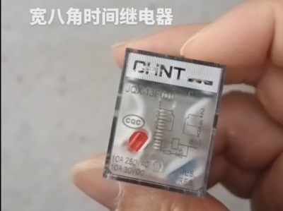
Chint JQX13F Electromagnetic Relay
-
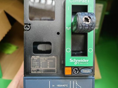
Schneider C16F2TM160 Circuit Breaker
-
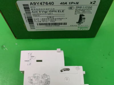
Schneider A9Y47640
-

Schneider LADN04C
-
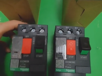
Schneider GV2ME08C motor circuit breaker
-
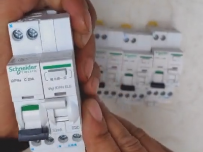
Schneider IDPNa C20A miniature circuit breaker (MCB)
-
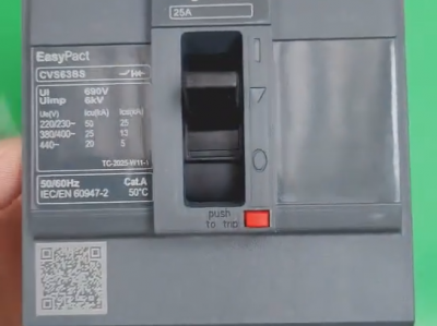
Schneider CVS63BS25A molded case circuit breaker (MCCB)
-
Schneider LC1DT80 4-pole contactors
-
Schneider Electric Circuit Breaker Model A9P28620